Front Dig Setup
After going to a local crawling competition, I quickly realized a few things. First, a WK Chassis is not going to win nationals this year. Second, if I wanted to even compete at the local level and finish a course, I need an ESC with a drag brake and a dig setup of some sort. I'm still researching ESC's but the dig setup was a bit more perplexing. My first thought was to try to slap in an R2D transmission from RC4wd. It has full function disconnect, freewheel & of course 4wd. The problems with that route are that I'm not sure it will fit in the WK chassis and the $104 price tag. Even if I did get one I'd want the full ball bearing version which is not out yet. So, in the interim, I decided to try a homebrew driveshaft disconnect.
I did some research on RCC and after looking at the different setups, and weighing my needs, I decided I should be able to make a decent setup, for under $30 (TX/RX not included). Keep in mind I had a lot of stuff already lying around form the HPI "Stage I" conversion, so your price tag may be more. My setup would only have the option of 4wd & dig/lock but in looking at it as I write this, I could do dig/freewheel as well. (Update to this - With the new radio, I actually set the servo center and end points so that I have all 3 choices, no more cutting/grinding necessary) . Regardless, since this setup is not for a hardcore comp tuber, I think it came out pretty well for what it is. My WK now can cut a turn on a dime and with the addition of a new ESC i think I will at least be able to have some fun at the next comp I go to.
PARTS & SUPPLIES NEEDED
Sticky sided Velcro
3 channel TX/RX (I use a TQ-3)
4 x 1/2" nuts (grade 5 is fine)
6-32 All-thread
3 x 6-32 lock nuts
1/8" thick, 2 in wide alum flat stock
Traxxas long half shafts #4951
6-32 rod end
2 x 2-56 rod ends
4-40 rod end (for servo)
HPI SF1 servo (or stronger)
HPI Wheely King Steering Lever I
K&S 1/4 x .49 Aluminum round tube
K&S 5/32 solid brass rod
Associated Servo Mounts #6336
Dubro LONG servo arm (from pack #670)
Assorted sandpaper
Masking tape
JB Weld
CA glue (thin is fine)
X-acto knife
Regular pen, gold paint pen & a sharpie
TOOLS
Dremel with cutoff disks & small grinding stones
Drill with assorted bits
Jigsaw with metal blades
4.5" Grinder
6-32 Tap
Cutting Oil
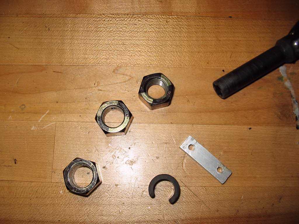
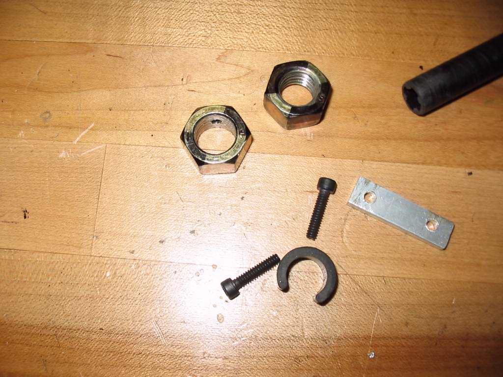
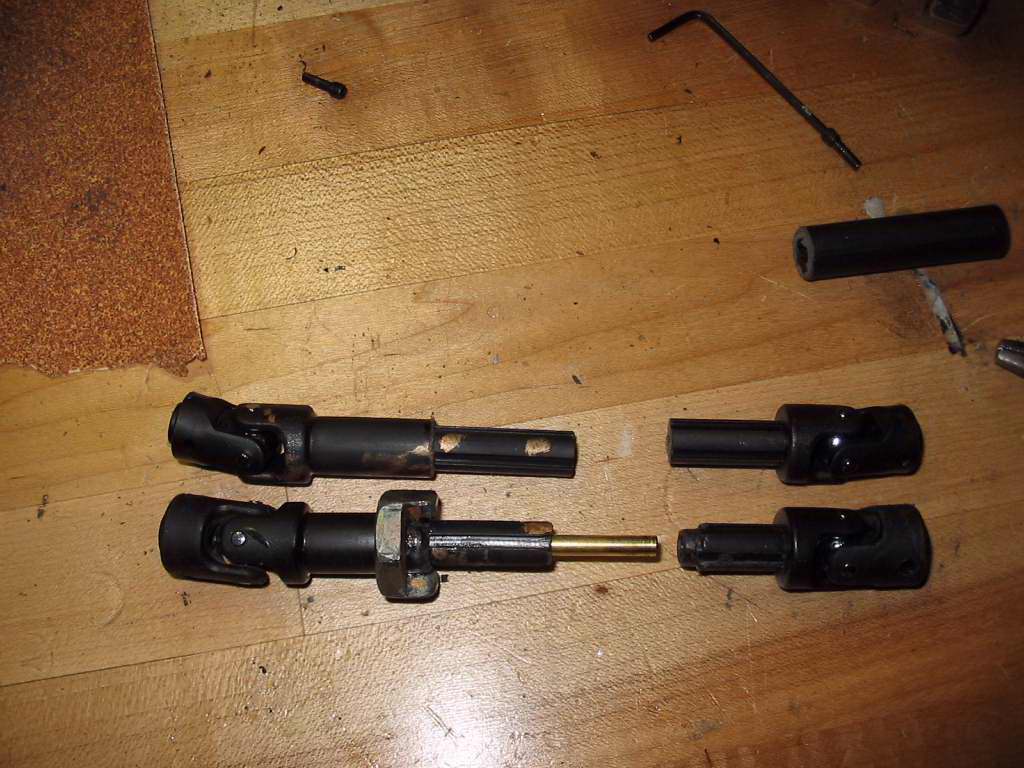
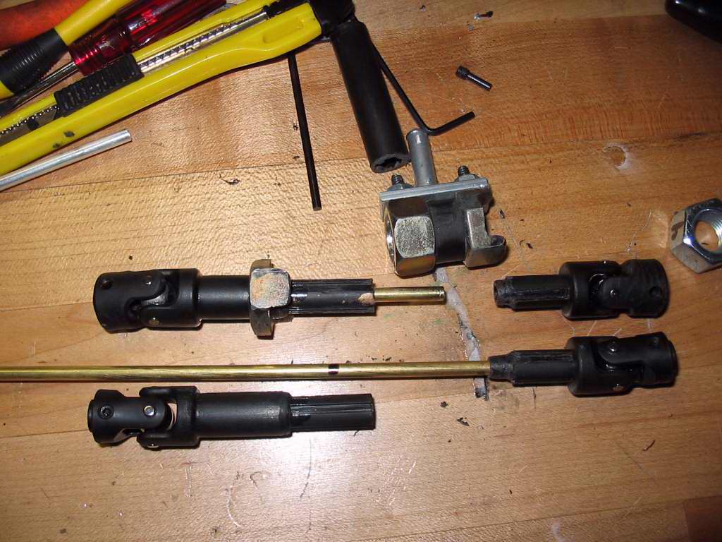
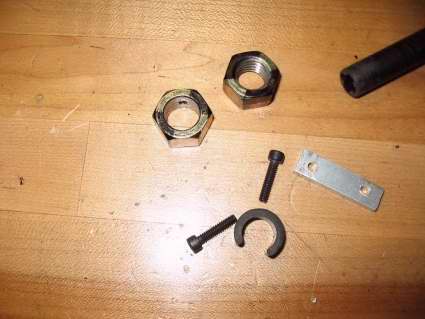
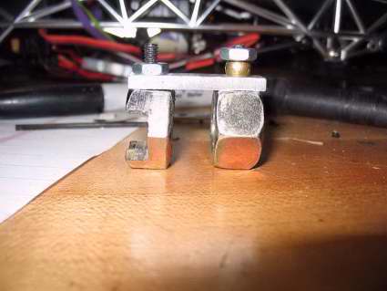
I actually went through 2 different setups as I was figuring this all out so some of the pictures don't match up perfectly but you'll get the idea. The stuff with the 8.8 (gold color) nuts was my first version.
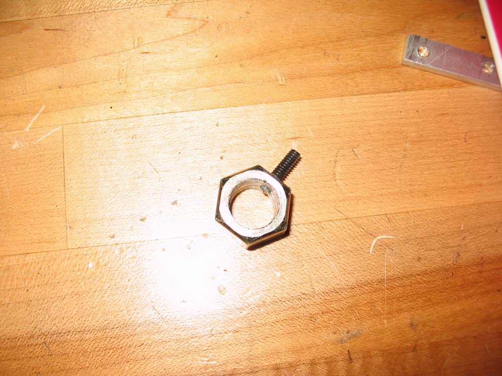
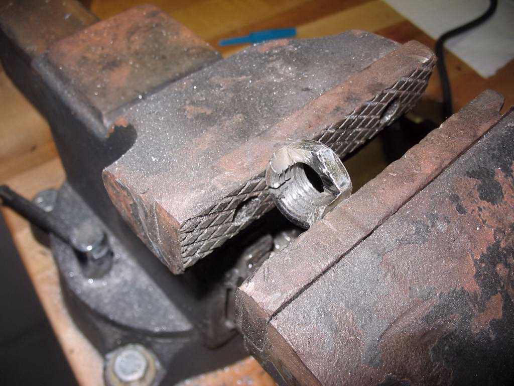
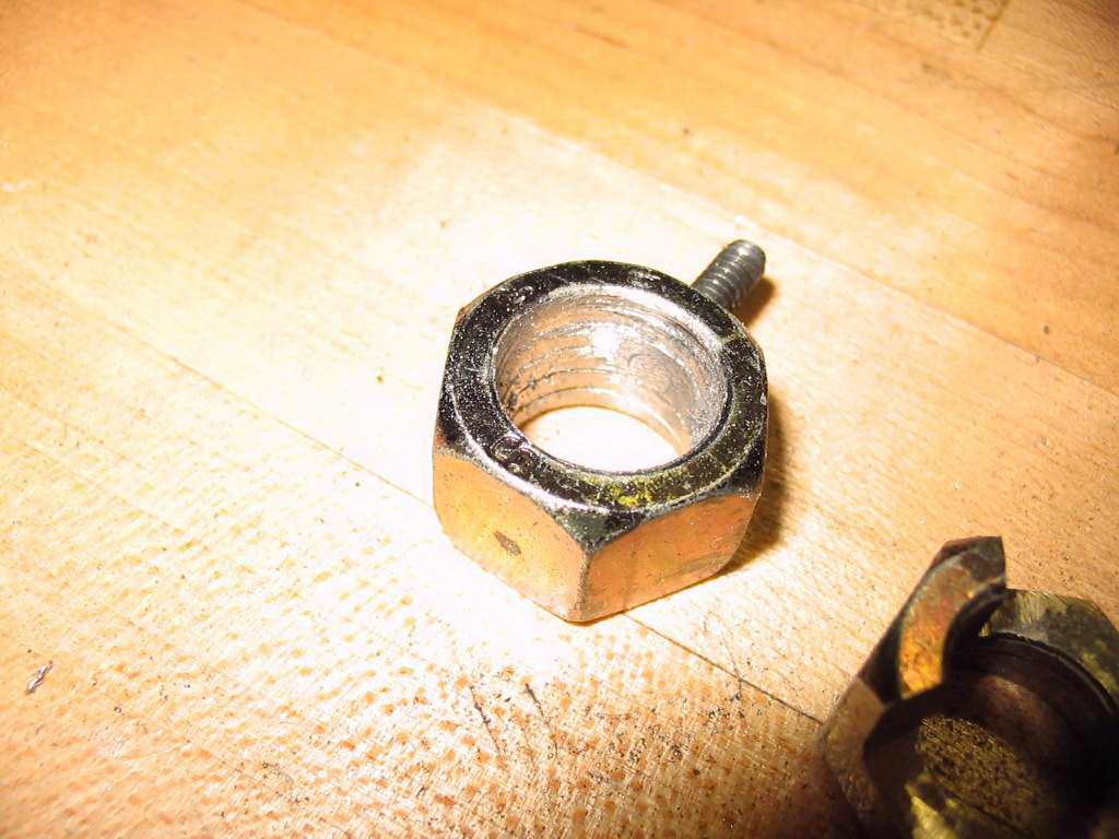
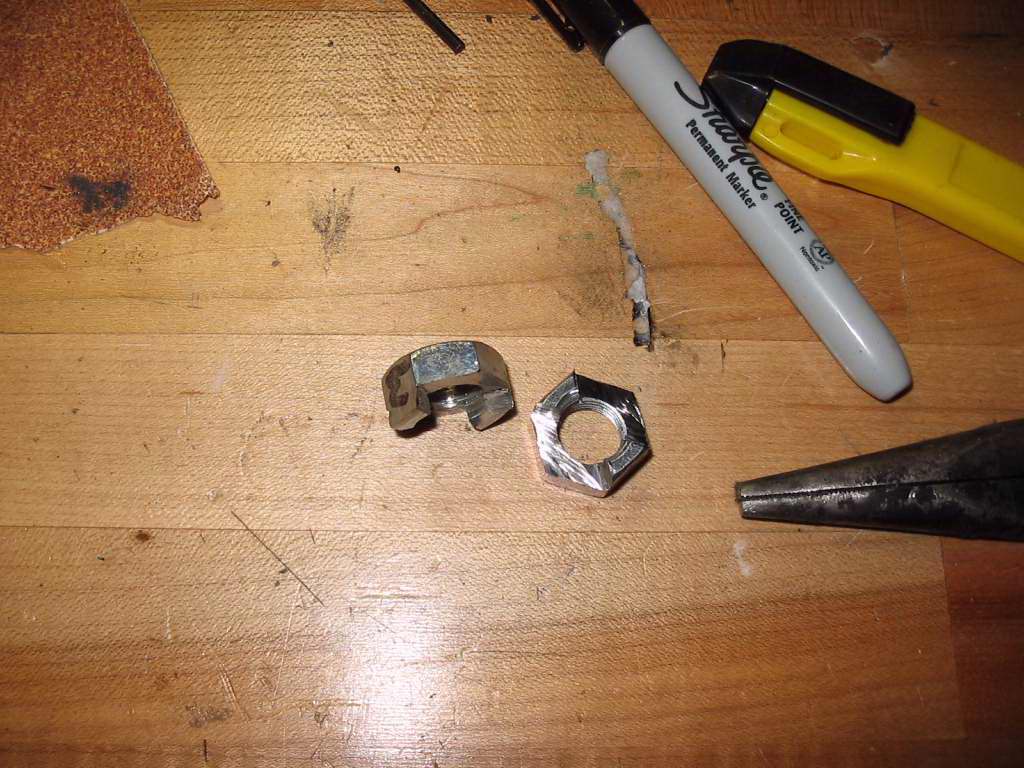
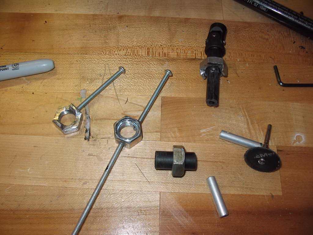
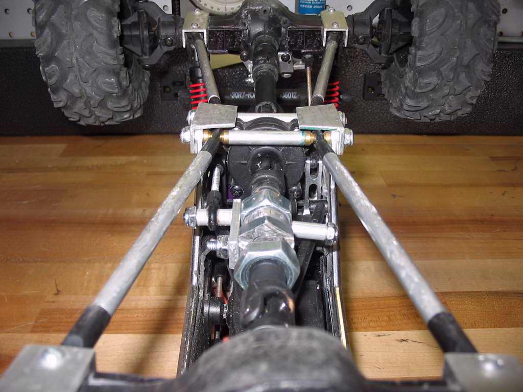
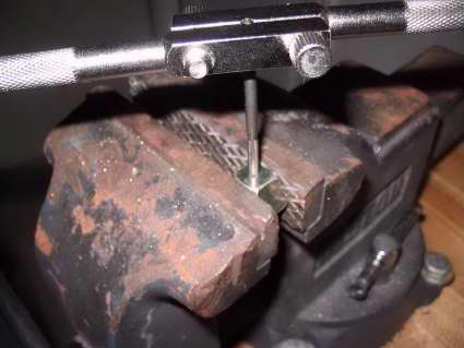
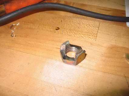
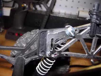
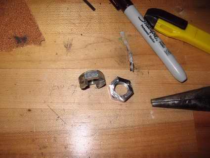
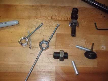
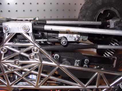
1. The first thing I wanted to figure out was how to make the dig collar. After looking at RCC for a while I came up with the following. First I mocked up and cut out a small piece of alum flat plate. Next (from front to back I used 4 1/2" nuts) #1 nut was tapped for 6-32 on two opposite sides and the 1/2" threads were drilled out to 15/32. #2 was cut down to about 66%, threads drilled out to 29/64 and grinded (angle grinder) to be a collar which would fit around the center piece of female driveshaft. #3 was dremeled to interlock loosly with #4. #3 was drilled out to 15/32 and tapped to 6-32 on one side. #4 interlocks with # 3 and was drilled out to 29/64. #1 will have long studs coming out of both sides that act as guides along the WK upper Y-arm. On one side, the guide on #1 will also attach to a rod end and clamp on a piece of alum that ties it to #3. Whew ... pictures are worth 1000 words....


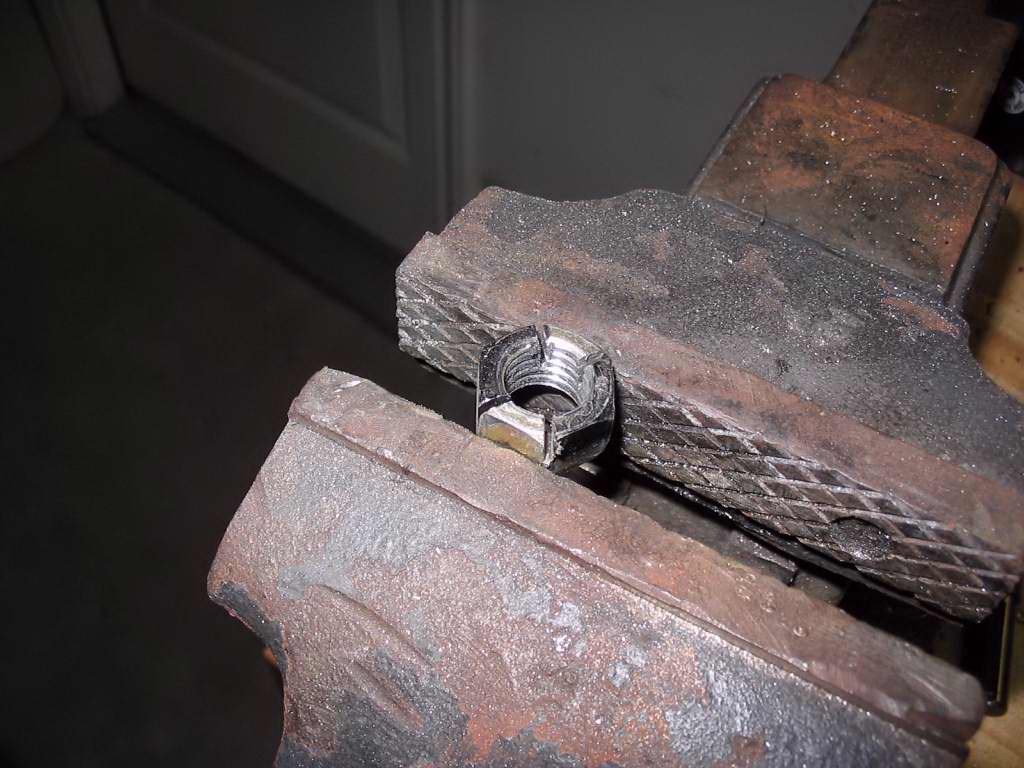
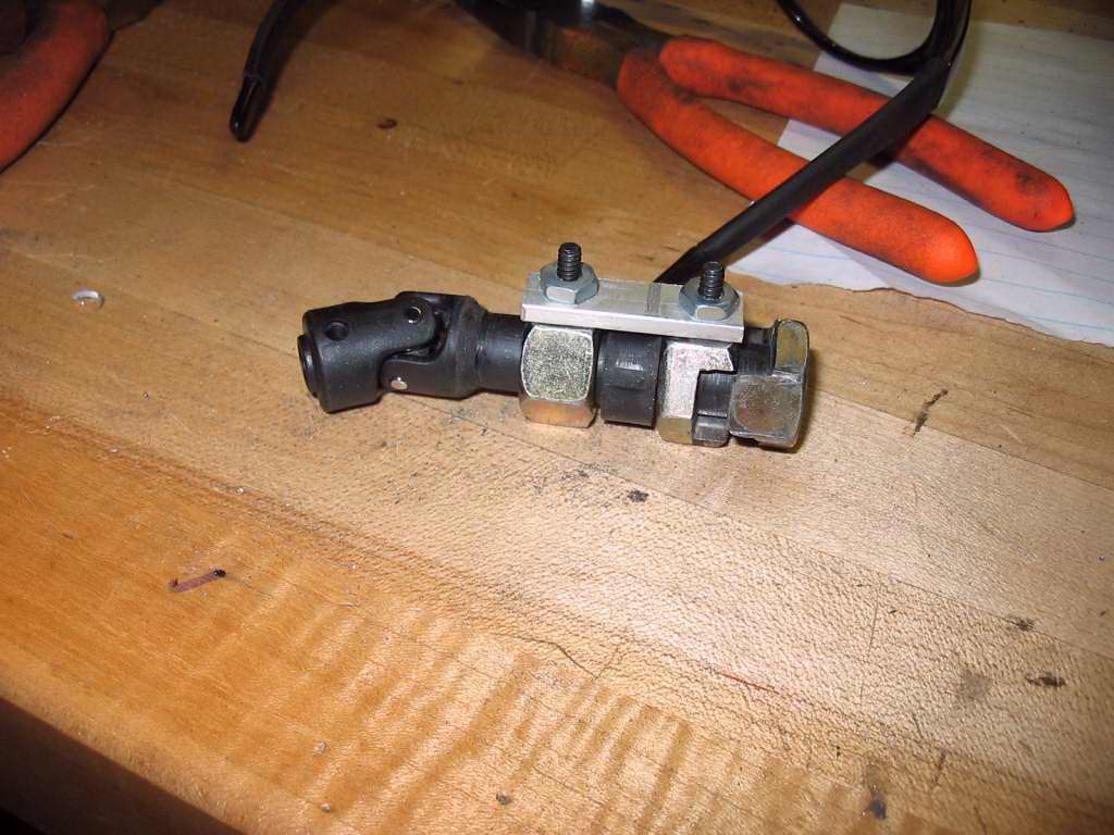
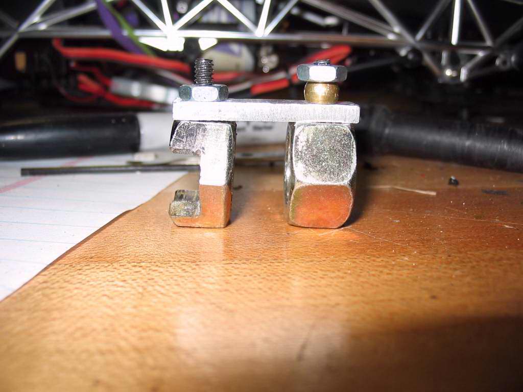
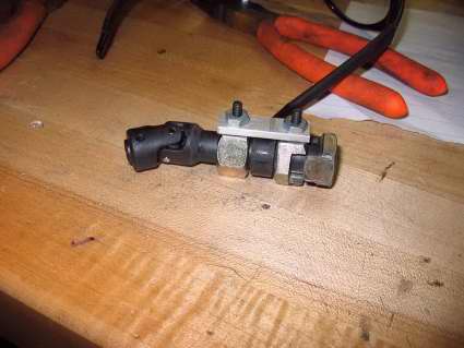
And now the assembled collar. A few tips on getting the nuts to work well... Fisrt, don't make the cuts deeper than they nee to be. If you setup the servo correctly, it will have constant pressure holding the two nuts together, so you don;t ned to make the "teeth" very deep. I actually cut mine way deeper than necessary. The second hint would be to bevel the edges so that they slide on and off of each other easily. You basicly want ot make sure there are no burrs and do a lot of test fitting before gluing anything.
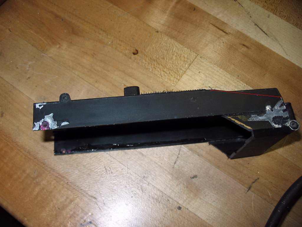
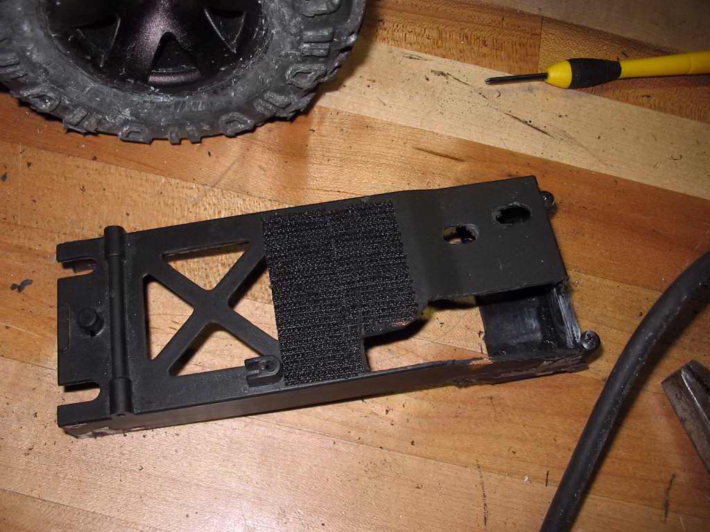
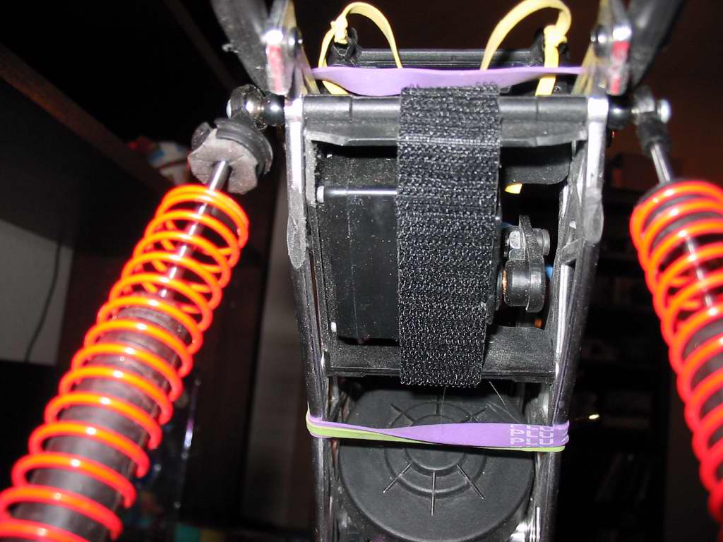
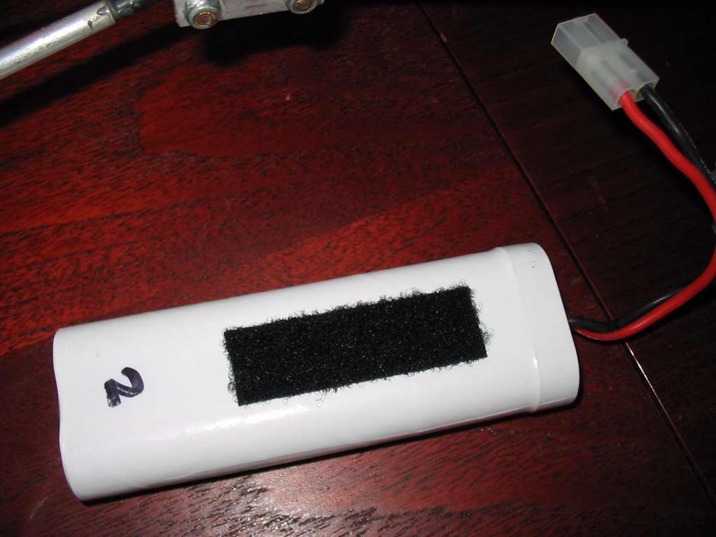
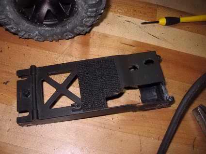
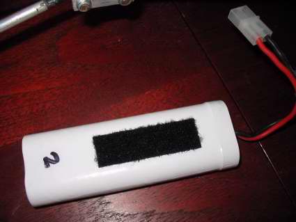
2. While I had it all apart, I decided to lower my battery tray a little and move my shocks rearward, but I don't think you have to. You will need to move your battery to the front though because your tray will now become home for your servo. To move the battery up front I put a piece of velco on the bottom of the servo (& my batteries) and using thick rubberbands I slide it in the front. Part of it sticks out, but I also run a front bumper to help protect it. It looks like the battery stop the suspension from compression fully, but it doesn't. I had also moved my "wheely bar" back a little to help prevent rollovers with the longer wheelbase, but it's not necessary for the dig setup. Anyway, you can see by the cutting (and red line where I had to go back and cut more) how I trimmed the battery box. Pretty easy part of the whole job.


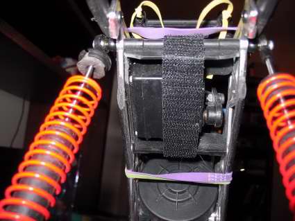
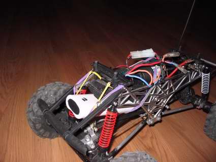
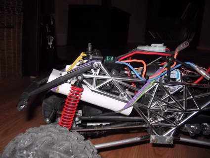
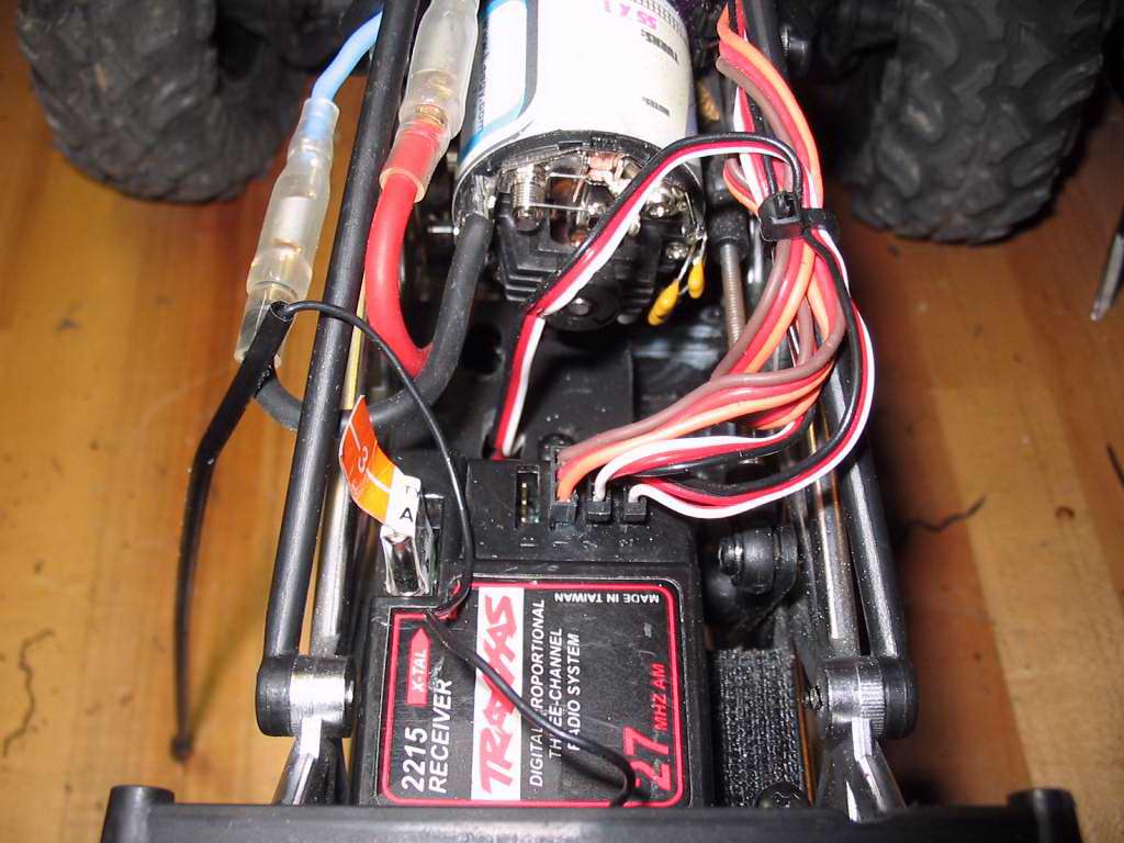
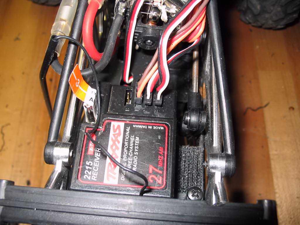
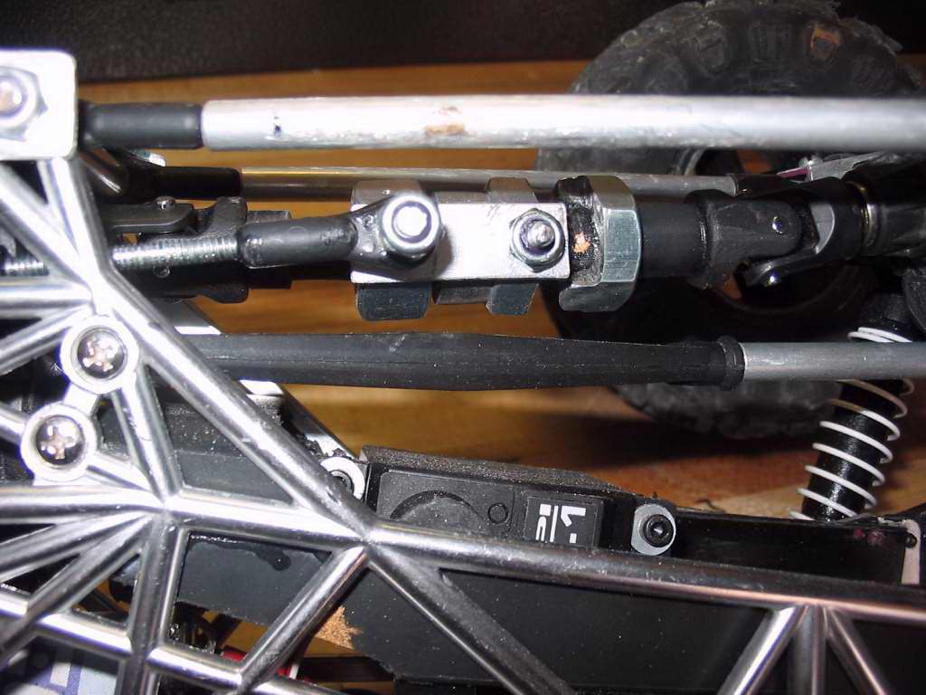
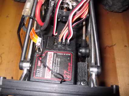
3. I also moved my ESC to the front and the RX to the rear. this was mostly due to getting a used RX with a short antenna wire, but it all fits nicely. In these shots you can see a little more of how I trimmed and mounted everything.

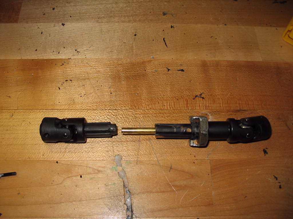
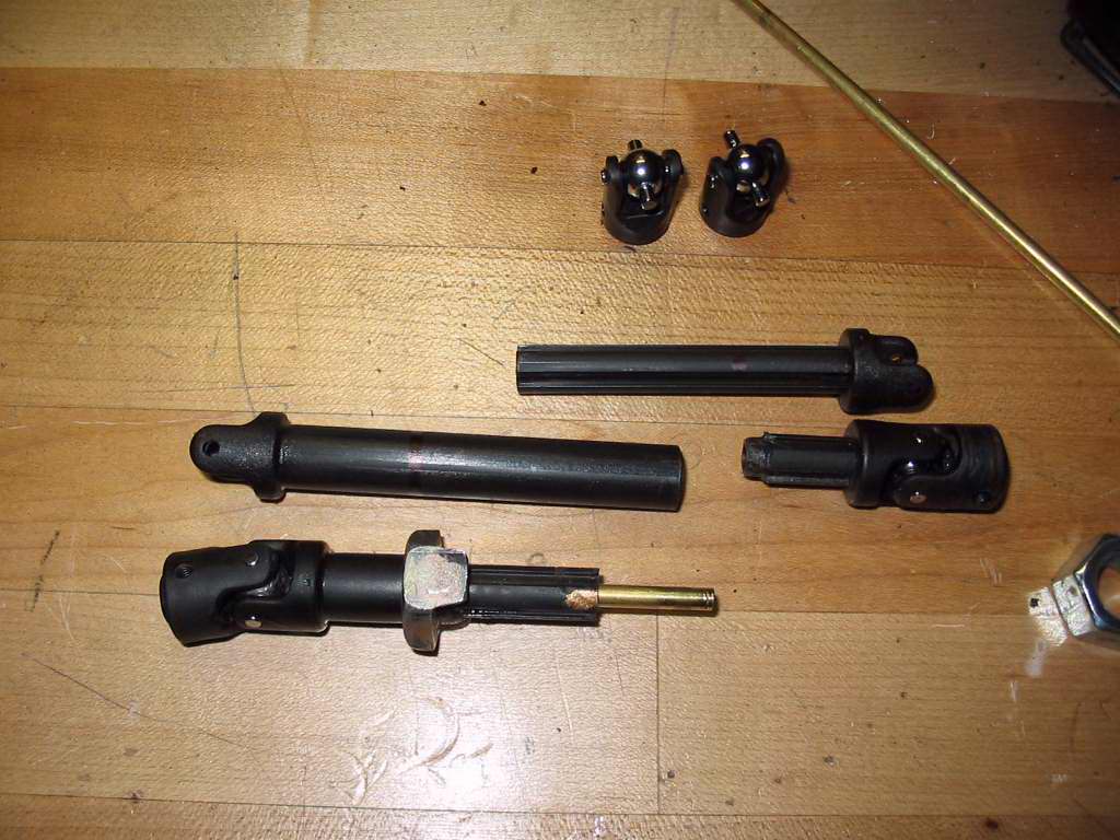
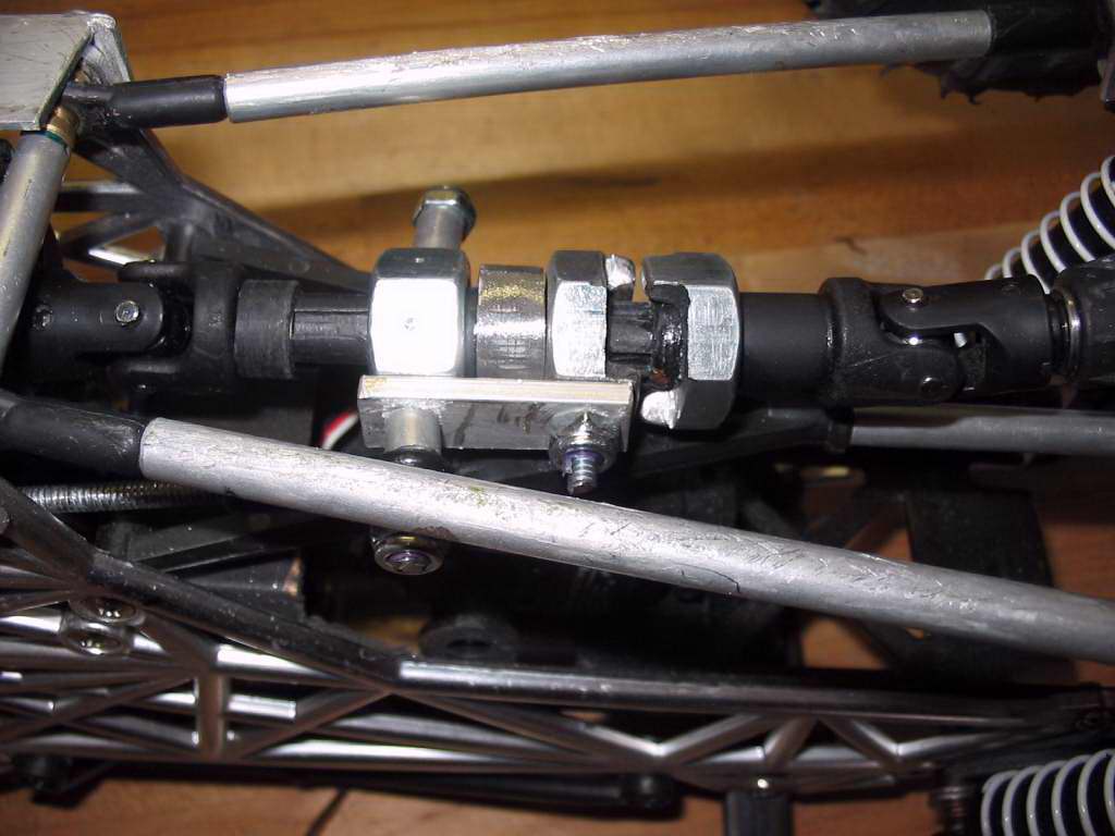
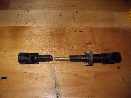
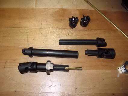
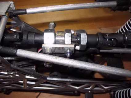
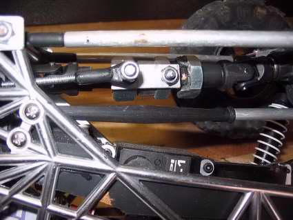
4. Here are a few more shots of my two different driveshaft attempts. Note that if you don't already run Traxxas shafts, you'll need to slightly drill out your WK yokes or buy Traxxas ones (I did one each way). You'll also find that the brass rod doesn't slip into the shafts perfectly, so you'll need to do a little drilling inside the shafts. For the shaft pieces themselves, I came out of the transmission with a male piece, cut to around 1 inch of spline showing. It also has about 3/8 inch of splines that were ground off. That ground off section allows the collar piece to freewheel a little while it transitions back onto the front piece & reconnects everything. Then of course you have the collar which is just a piece of female shaft with the assorted nuts. The last segemnt is a combination of male & female shaft parts & the #4 nut. I can;t explain how exactly to grind everything down better than the pictures can but just make sure you take your time and check & recheck everything before you glue anything. In the end, the #3 nut (ground to a collar), gets pressed onto the female shaft collar & glued. #4 nut gets pressed onto the second (axle side) shaft piece and glued. You will also glue the male piece of shaft into that rear female section. I glued the brass rod into the front male secton but you can glue it into either one. just make sure it all spins freely.


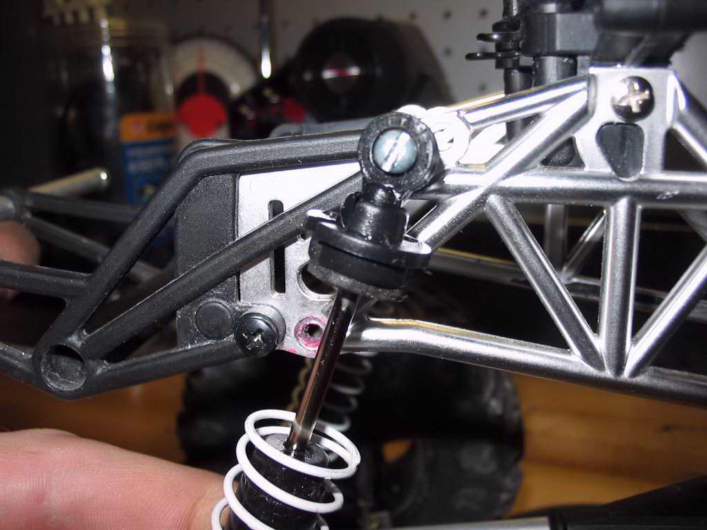
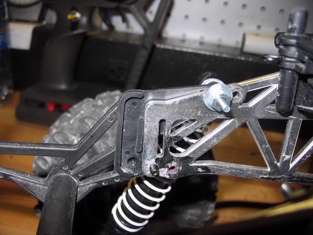
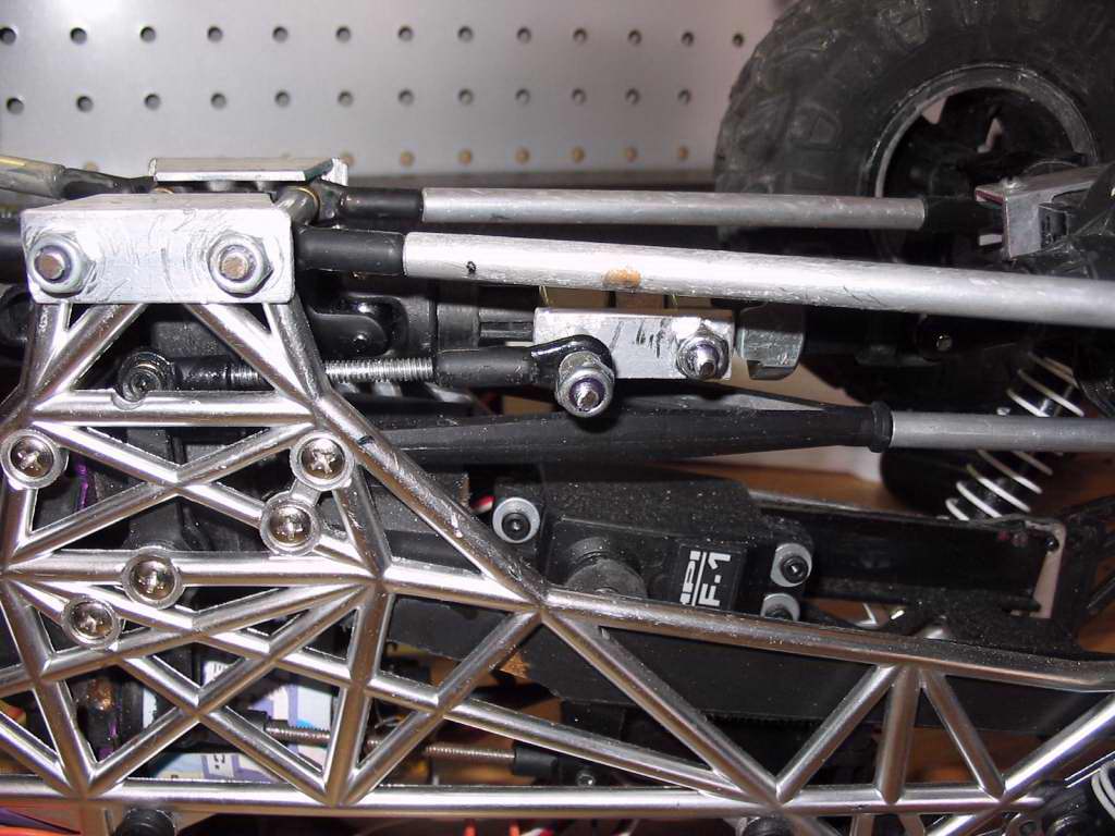
5. Things I haven't mentioned so far ar that you'll need to install a second (or put your original back in) steering lever I. The catch is it will go on the other side (in my case driver side). You also need to cut out some links to attach the servo to the steering lever I and to attach that to the collar. It's pretty obvious once you get all the parts together and look at the pictures.
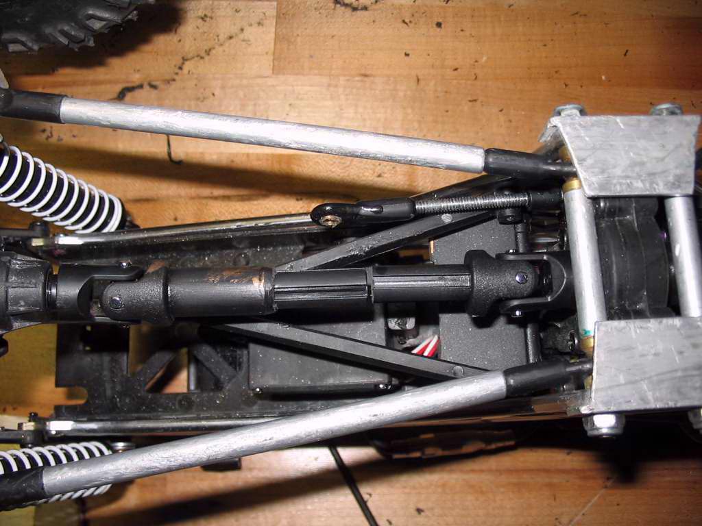
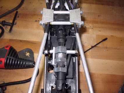
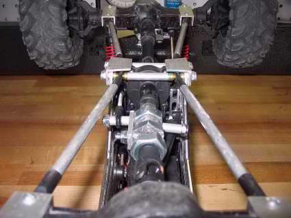
6. Here it is all put together. I know I didn't do the best job explaining this one but I think the pictures tell the story.
Here is a little video of the setup in action:
Initial Testing
Original setup
Final Setup
Final thoughts....
After using the heck out of the setup for a few days without any major issues, I have made a few changes:
1. I changed to the middle hole on the servo horn. This removed some of the movement, but gave the arm a little more torque.
2. I bumped up the output on my CC BEC to 6.6volts. This made a big difference in how much power the servos have. Not all of you will have the CC BEC but installing a better servo would have a similar result.
3. I also installed another Tower Pro servo and it made a big difference, especially running at 6.6v
4. I installed (not pictured) an aluminum upper A-arm link. The whole thing slides a lot better now.
5. Lastly,m as stated before, I was able to acheive a full 3 function setup with the new radio.